445009, Самарская обл., гор. Тольятти,
ул. Новозаводская 2а, стр. 309
ул. Новозаводская 2а, стр. 309
Извещатели комбинированные предназначены для установки в местах где нельзя однозначно спрогнозировать возникновения и развития пожара (первичное возникновение дыма или повышение температуры). Компенсация запыления дымовой камеры обеспечивает сохранение чувствительности извещателя на установленном уровне и отсутствие ложных срабатываний, а также существенно увеличивает периоды эксплуатации между техническим обслуживанием. Извещатель соответствует ТР ЕАЭС 043/2017.
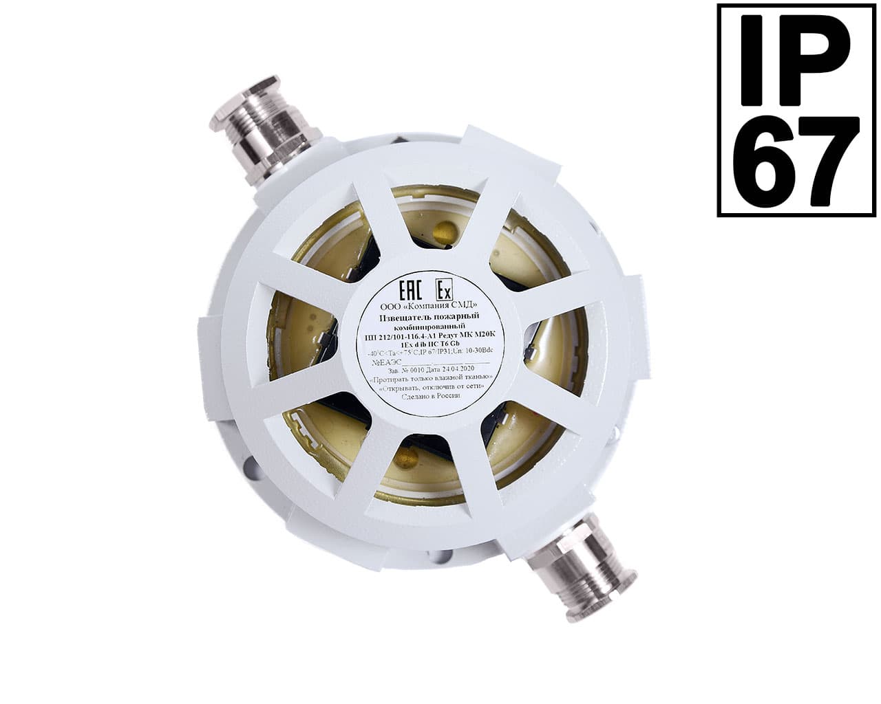
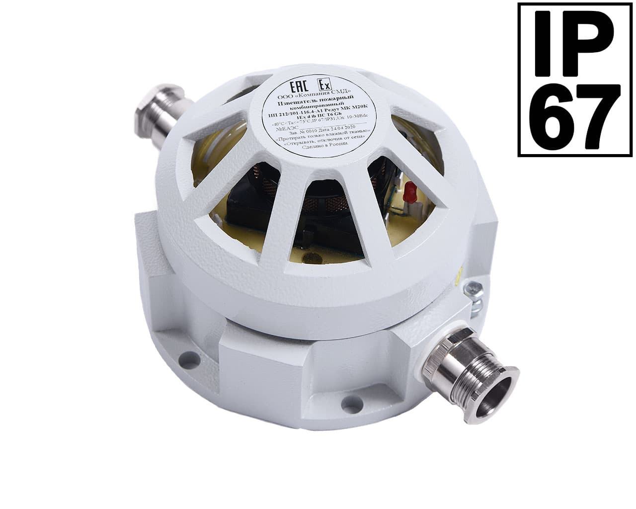
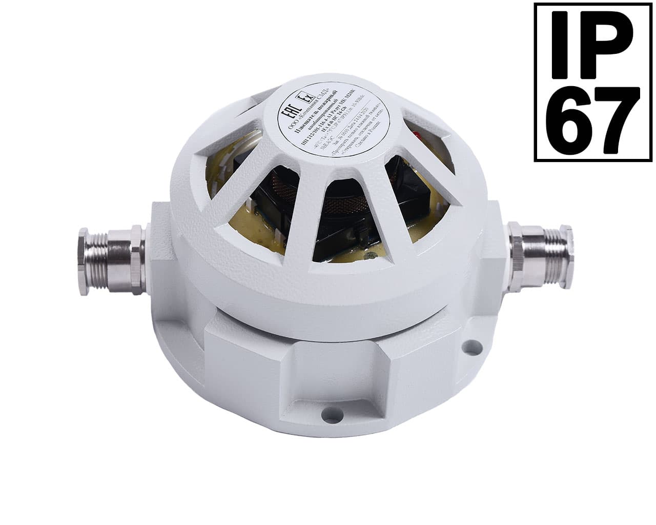
Извещатели рассчитаны на эксплуатацию при температуре окружающей среды от минус 40°С до плюс 75°С, вид климатического исполнения УХЛ категории 2, относительная влажность воздуха 93% при температуре не более 400С. Атмосферное давление от 84 до 106.7 кПа. Уплотнения и соединения элементов конструкции корпуса извещателя обеспечивают степень защиты по ГОСТ 14254-2015 (IEC 60529:2013) «Степень защиты, обеспечиваемые оболочками (Код IP)» коммутационного отсека – не ниже IP67; дымовой камеры – не ниже IP31.
Материал корпуса – коррозионностойкая нержавеющая сталь 12Х18Н10Т.
По способу защиты человека от поражения электрическим током извещатель соответствует III классу по ГОСТ 50571.3.
Извещатели соответствуют нормам и требованиям электромагнитной совместимости по ГОСТ Р 53325 со степенью жесткости испытаний 2. Радиопомехи от извещателя не превышают норм, установленных ГОСТ 30805.22 для оборудования класса Б.
ИП 212/101-116.4-А1 Редут МК-ОП – Н является извещателем максимально-дифференциального действия и может использоваться в шлейфах сигнализации на замыкание (параллельное включение).
Извещатели комплектуется двумя кабельными вводами серии КВ, KV ТУ 27.33.13-359-81888935-2019. Присоединительная резьба кабельных вводов М20х1,5. Кабельные вводы позволяют ввести и вывести кабели круглого сечения различных диаметров:
| Степень защиты оболочки | IP67 / IP31 |
| Диапазон рабочих температур | -40°С .. +75°С |
| Диапазон напряжения питания | от 10 до 30В |
| Ток потребления: | |
| в дежурном режиме, не более | не более 0,25 мА |
| в режиме тревога, не более | не более 20 мА±3% или 5мА±1% |
| Чувствительность извещателя | |
| дымового датчика извещателя | не менее 0,05 и не более 0,2 дБ/м |
| тепловой при окружающей среде (54…65) °С и более | соответствует классу А1 п. 4.5.1.2 ГОСТ 53325 табл. 4.1 |
| Время срабатывания извещателя, не более | 10 сек |
| Значение электрического сопротивления изоляции | не менее 20 МОм |
| Значение электрической прочности изоляции | не менее 0,75 кВ |
| Средняя наработка на отказ в дежурном режиме | не менее 60000 ч |
| Средний срок службы | не менее 10 лет |
| Материал корпуса | нержавеющая сталь |
| Масса | не более 4,7 кг |
| Габаритные размеры без кабельных вводов | 150х146х105мм |
Таблица 1.
| Режим работы | Индикация | Состояние |
| Пожар | непрерывное свечение | Срабатывание извещателя |
| Дежурный | Прерывистое свечение с периодом 4 сек. | Нормальная работа |
| Запыленность | Двойные вспышки с периодом 1 сек. | Работоспособен, но требуется обслуживание: произвести чистку камеры |
Пример обозначения извещателя при заказе:
| ИП | Х1Х2Х3 | Х3 | – 116.4 – | Х4 | Редут | X5 | X6 | X7 |
| 1 | 2 | 3 | 4 | 5 | 6 | 7 | 8 | 9 |